Back to basics: LED
In the last two posts, we've been mainly focussing on inputs. Pushbuttons send a command to the game, and rotary encoders twist up those frequencies like there is no tomorrow. Like human relationships, it's important to receive something occasionally instead of constantly sending data. Perhaps LEDs sound dull, stupid, and simple, and you might be right. But when speaking for myself, I know that I've burnt the LED or two, overvolted a 7 segment display (basically separate LEDs) and installed them backward. I always followed tutorials that told me which resistor to use. But not anymore! If you recognize yourself in these previous statements, don't worry. We'll dive deeply into how LEDs work and how to use them to display several statuses.
Cathodes and anodes
Default LEDs have an anode and a cathode side. The best way to visually spot the difference is to check the length of the legs. The anode side (the longer leg usually represents the + side). It would help if you spotted the anode side with a smaller lead inside the LED while the cathode (the ground side) has a larger lead. This last part will become more important for RGB LEDs, which we'll discuss later.
A term you might have heard of is common anode or common anode. This term is often used for LED panels, 7-segment displays, and even RGB LEDs. But what does it exactly tell us? A common anode device tells us multiple LEDs use a shared anode (+/power) lead. They usually share their anode while having their cathode leg. We could flip the logic for common cathode devices with a common cathode line (ground). Each LED will be powered by its anode inputs (power) and ditch its current over the same cathode (ground) leg. With this knowledge, we can take a look at RGB LEDs.
RGB LEDs
RGB LEDs have multiple leads that let you control their color. RGB refers to Red, Green, and Blue. These primary colors can be combined to create many mixed colors. I've bought several RGB LEDs over time, and they all were common cathode lights. According to sources, there are also common anode RGB LEDs available. The common cathode/anode line can be found by looking for the longest leg on the LED. To determine if it's a common cathode LED, you should look inside it to see if the longest leg also has the largest lead. If this is the case, we know we are dealing with a common cathode, an RGB LED (Which will be the most common).
(KEEP READING BEFORE YOU PLUG ANYTHING IN)
Using a simple digital signal, we could display the primary colors by connecting 1 of the anode legs to our 5v line and the common cathode line to the ground. Just swapping the anode leg around would cycle between all three colors.RGB light, Green -> Red -> Green + RED
Resistors
Now, if you have not been paying attention to my warning, there is a chance you've already blown through your first LED. Most LEDs will suffer a horrible death when hooked up directly to your power source. Even if the LED would hold on for its life, the light emitted will probably be too bright to look at comfortably.
To prolong the lifespan of our LED, we use resistors. Resistors reduce the limit flow. How much they reduce the flow depends on the ohmage (resistance value). We could calculate the minimum resistor power we need with the following formula:
R = (Vs - VLed) / Iled
- R is the resistance expressed in ohms.
- Vs (source voltage)
- Vled (the voltage drop from the LED in volts)
- Iled (the current through the LED in mA)
Most of these values can be found on the spec sheet of the LED you've bought. For this example, I've taken the following product info from Amazon:

The first thing that stands out is the difference depending on the color used. White, Green, and blue have a forward voltage of ~3V, while red and Yellow have a forward voltage of ~2V. If we throw these values(for a blue LED) in our formula, we would get the following:
R = (5000 - 2000) / 20 = 150Ohm
Various sites offer free calculators for this purpose. But in reality, most hobbyists don't have to pinpoint the exact minimum ohmage. Even though there is some variance between various LEDs, the resistance used will usually become a matter of taste. Don't forget that his calculation will give you the MINIMUM value required. This LED will usually still be too bright (at least for my taste). If this is the case, you can always increase the ohmage.

The image above shows 4 similar LEDs but with different resistors. The first one is a 1k resistor (1k = 1000 Ohm), followed by a 500r (500r = 500Ohm), 274R, and 5k. The 5k barely turns on, while the 274R is too bright. Getting the desired result will come down to testing and fooling around with variable resistance values.
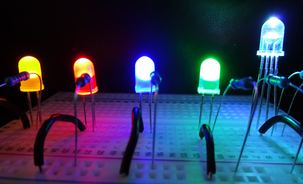
As I mentioned earlier, color can also influence brightness. In the picture above, the green and blue lights seem brighter than the yellow and red lights, even though they all use the same Ohmage.
How to code with LEDs
Let's take a look at how to code up our LEDs. Everything I've mentioned above can be achieved with only 5V power and ground lines. If a lit LED were all we wanted to achieve, we might as well hook them up directly to a battery and leave out the Arduino. So it's about time we take back some control.
In the first paragraph, I already said that we would work with outputs. It is important for our Arduino to understand that it can send signals to the LED. This allows us to differentiate between digital and analog writing.
The schematic used in my examples
Digital signal
Digital write is the simplest solution. It will either set a signal to HIGH or LOW. There is no brightness scale, which can only be controlled by increasing/decreasing the resistance. The code would look like this:
cpp#include <BitsAndDroidsFlightConnector.h>
BitsAndDroidsFlightConnector connector(false);

//const tells us the pin value changes
//Since we won't be moving the cable we declare the pin as a constant
const byte ledPin = 3;

void setup() {
  Serial.begin(115200);

  //the led pin will send a signal out but will never receive a signal
  pinMode(ledPin, OUTPUT);
}

void loop() {
  //TURN THE LED ON
 digitalWrite(ledPin, HIGH);
 delay(1000);
 //TURN THE LED OFF
 digitalWrite(ledPin, LOW);
 delay(1000);
}
I've already included the flight connector library, which we will use down the road. This sketch might look familiar since most Arduino tutorials start with a similar sketch. It will turn the LED on, wait 1 sec, turn the LED off, wait 1 sec, and repeat until we unplug the device. The HIGH will turn the LED fully on, while the LOW will turn it completely off.
Analog write
Ever noticed the squigly lines in front some of the pins?

These indicate that the pin can be used to send a PWM signal. A PWM (pulse width modulation) signal creates a wave at variable rates, making the LED appear brighter or dimmer. The name ANALOG write might seem confusing since A: you can't use the Analog pins on your board to analogWrite. And B: PWM isn't analog. It only creates an "analog" looking effect. It switches the LED on and off at precise rates to make them appear dimmer / brighter.
cpp#include <BitsAndDroidsFlightConnector.h>
BitsAndDroidsFlightConnector connector(false);

//const tells us the pin value changes
//Since we won't be moving the cable we declare the pin as a constant
const byte ledPin = 3;

void setup() {
  Serial.begin(115200);
  //the led pin will send a signal out but will never receive a signal
  pinMode(ledPin, OUTPUT);
}

void loop() {
  //TURN THE LED FULLY ON
 analogWrite(ledPin, 255);
 delay(1000);
 //TURN THE LED DIMMER ON
 analogWrite(ledPin, 100);
 delay(1000);
}
The analogWrite function takes a value between 0 and 255. 0 turns the signal off, while 255 turns it fully on.
Important note about 10uf capacitor (mega, uno, nano)
If you use a different Arduino than a Leonardo or Pro-micro (Atmega 32u4 chip-based Arduinos), this section may apply to you (i.e., the Uno, mega, or nano). If you are using these boards to retrieve data from the game, you must place a 10uf capacitor between the ground and the reset button. This ensures that the Arduino doesn’t reset every time it receives data. When uploading a new sketch, removing the capacitor from the board is important.
This doesn’t apply to boards from brands like the STM32 or Teensy.
Game states
LEDs are perfect for displaying certain states in the Microsoft flight simulator. Is the autopilot on, gear down, my landing lights on, etc.? All questions can be answered with a yes or no. For this, we're going to make use of booleans and if statements. The parameter for an if statement is just a boolean. if(1 == 3){ } will become if(false), so the code block won't be executed (an if statement only runs if the statement returns true). Now, a whole bunch of Boolean states are ready to be used in the connector (see the documentation). I've listed just a few down below as an example.
Taxi lights.getLightTaxiOn()boolean false = off, true = onStrobe lights.getLightStrobeOn()boolean false = off, true = onPanel lights.getLightPanelOn()boolean false = off, true = on
Now, turning a light on or off could become something like this:
cpp#include <BitsAndDroidsFlightConnector.h>
BitsAndDroidsFlightConnector connector(false);

//const tells us the pin value changes
//Since we won't be moving the cable we declare the pin as a constant
const byte ledPin = 3;

void setup() {
  //the led pin will send a signal out but will never receive a signal
  Serial.begin(115200);
  Serial.setTimeout(15);
  pinMode(ledPin, OUTPUT);
}

void loop() {
 //This ensures the Arduino keeps listening for game updates comming from the connector
  connector.dataHandling();
 // if the landing lights return true
 if(connector.getLightLandingOn()){
    digitalWrite(ledPin, HIGH);
    delay(1000);
 }
 //The exclamation mark tells us the statement has to be false
 else if(!connector.getLightLandingOn()){
   digitalWrite(ledPin, LOW);
  delay(1000);
 }
}
When we use the connector to receive data, it's important to include the connector.dataHandling(). Selecting the data to be received before hitting start is also important. This ensures we don't overload our Arduino with values we'll never use.

Select the desired outputs in the connector.
1's and 0's
If we follow the mantra that everything in the world of computers is either 1s or 0s, we could even shorten our code significantly. HIGH is just another front for a 1. True also is a front for a 1. The same goes for LOW being a front for 0 and false being a front for 0. Let's see how we can manipulate this information into simple code:
cpp#include <BitsAndDroidsFlightConnector.h>
BitsAndDroidsFlightConnector connector(false);

//const tells us the pin value changes
//Since we won't be moving the cable we declare the pin as a constant
const byte ledPin = 3;

void setup() {
  Serial.begin(115200);
  Serial.setTimeout(15);
  //the led pin will send a signal out but will never receive a signal
  pinMode(ledPin, OUTPUT);
}

void loop() {
  connector.dataHandling();
  digitalWrite(ledPin, connector.getLightLandingOn());
}
Here we combined the if on or off statement into a clean one-liner.

Instead of using off-the-shelve booleans, we could also make our own statements.
#include <BitsAndDroidsFlightConnector.h>
BitsAndDroidsFlightConnector connector(false);

//const tells us the pin value changes
//Since we won't be moving the cable we declare the pin as a constant
const byte ledPin = 3;

void setup() {
  Serial.begin(115200);
  Serial.setTimeout(15);
  //the led pin will send a signal out but will never receive a signal
  pinMode(ledPin, OUTPUT);
}

void loop() {
  connector.dataHandling();
  byte landingGearPercentage = connector.getGearTotalPct().toInt();
  //One-line for if(landingGearPercentage >= 99){}
  digitalWrite(ledPin, landingGearPercentage >= 99);
}
Fly!
I could probably go on about this subject, but we've covered most of the basics required for you to start. After making it this far, you can proudly call yourself a master of the LEDs. If you have any questions, leave them in the comments below, and have fun!